因果回路图
本词条由春虫虫初步翻译。
因果回路图Causal Loop Diagram是一种因果图,有助于可视化地显示系统中不同变量之间的相互关系。该图由一组节点和边组成。节点代表变量,边代表两个变量之间的链接或者关系。标记为正的链接表示正向关系,标为负的链接表示负向关系。正因果链接意味着两个节点在同一方向上发生变化,也就是说,如果链接起始的那个节点减少,则链接的另一个节点也会减少。类似地,如果链接的起始节点增加,则链接的另一个节点也会增加。负因果链接意味着两个节点在相反的方向变化,即,如果链接的起始节点增加,则另一个节点减少,反之亦然。< br/>
闭合回路是因果回路图的重要特征。一个闭合回路要么是强化回路Reinforcing Loop,要么是平衡回路Balancing Loop。强化回路中,任何变量发生变化所造成的影响会通过回路进行传播后回到这个变量,并强化这个变量的初始偏差。也就是说,一个变量增长后,强化回路的作用会使得这个变化沿着回路返回给这个变量一个增量,反之亦然。平衡回路中,任何变量发生的变化会沿着回路传播并返回给该变量一个与初始偏差相反的偏差。也就是说,如果一个变量增加,经过平衡回路的作用会使得返回给该变量一个减少值,反之亦然。
如果一个变量在强化回路中发生变化,这种变化的作用会加强初始变化。这种变化的作用会产生另一种强化效果。如果不打破这个回路,系统会陷入循环链式反应的恶性循环中。正是因为这个原因,闭合回路成为了因果回路图的关键特性。
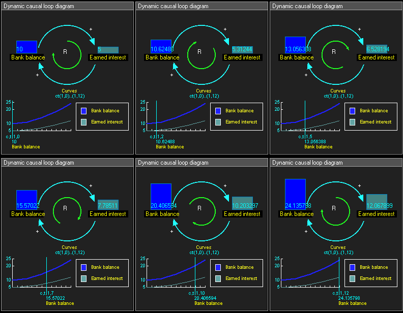
正向强化循环的例子:
- 银行余额将影响已获利息,如顶部从银行余额指向已获利息蓝色箭头所示。
- 由于银行余额的增加会导致已获利息的增加,所以这个链接是正的,用“+”表示。
- 已获利息被添加到银行余额中,这也是一个正链接,由底部的蓝色箭头表示。
- 这些节点之间的因果关系形成了一个正的强化回路,用绿色箭头表示,用“R”表示。[1]
历史
The use of nodes and arrows to construct directed graph models of cause and effect dates back to the invention of path analysis by Sewall Wright in 1918, long before System Dynamics. Due to the limitations of genetic data, however, these early causal graphs contained no loops — they were directed acyclic graphs. The first formal use of Causal Loop Diagrams was explained by Dr. Dennis Meadows at a conference for educators (Systems Thinking & Dynamic Modeling Conference for K-12 Education in New Hampshire sponsored by Creative Learning Exchange ).
使用节点和箭头构造因果有向图模型的历史可以追溯到Sewall-Wright在1918年提出的路径分析,比系统动力学早很多。然而,由于遗传数据的限制,这些早期的因果图不包含回路——它们是有向无环图。Dennis Meadows博士在一次教育工作者会议上解释了因果回路图,这是因果回路图的第一次正式使用。[2]).
Meadows explained that when he and others were working on the World3 model (circa 1970–72), they realized they would not be able to use the computer output to explain how the feedback loops worked in their model when presenting their results to others. They decided to show feedback loops (without the stocks, flows and every variable), using arrows connecting the names of major model components in the feedback loops. This may have been the first formal use of Causal Loop Diagrams.
Meadows 解释说,当他和其他人在研究 World3模型(大约在1970-1972年)时,他们意识到在向他人展示结果时,他们无法使用计算机输出来解释反馈回路在模型中的工作方式。他们决定通过用箭头连接反馈循环中主要模型组件的名称来展示反馈循环(不包括库存、流量和每个变量)。这可能是第一次正式使用因果回路图。[3]
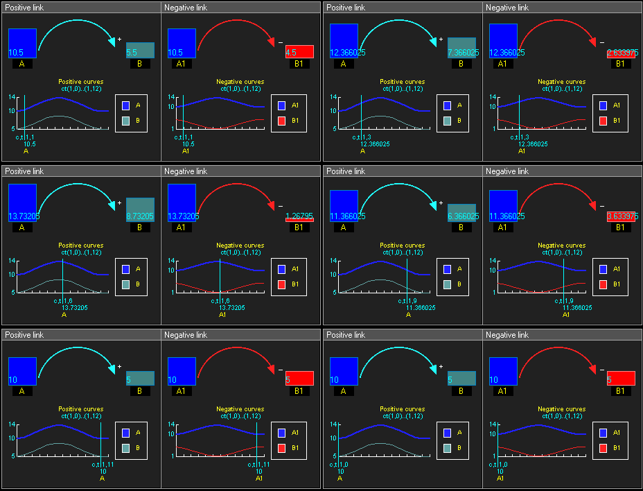
正向和负向的因果链接
- 正因果链接 意味着两个节点在同一方向上发生变化,也就是说,如果链接起始的那个节点减少,则链接的另一个节点也会减少。类似地,如果链接的起始节点增加,则链接的另一个节点也会增加。
- 负因果链接 意味着两个节点在相反的方向变化,即,如果链接的起始节点增加,则另一个节点减少,反之亦然。
示例
强化回路还是平衡回路
To determine if a causal loop is reinforcing or balancing, one can start with an assumption, e.g. "Node 1 increases" and follow the loop around. The loop is:
为了确定一个因果回路是强化的还是平衡的,可以从假设开始,例如“节点1增加”,然后跟踪回路。回路是:
- “增强”的,如果在循环之后,得到的结果与最初的假设相同。
- “平衡”的,如果在循环之后,得到的结果与最初的假设相反。
或者换句话说:
- reinforcing loops have an even number of negative links (zero also is even, see example below)
- 强化回路中
- balancing loops have an odd number of negative links.
Identifying reinforcing and balancing loops is an important step for identifying Reference Behaviour Patterns, i.e. possible dynamic behaviours of the system.
识别强化和平衡回路是识别参考行为模式(即系统可能的动态行为)的重要步骤。
Identifying reinforcing and balancing loops is an important step for identifying Reference Behaviour Patterns, i.e. possible dynamic behaviours of the system.
- Reinforcing loops are associated with exponential increases/decreases.
If the system has delays (often denoted by drawing a short line across the causal link), the system might fluctuate.
如果系统有延迟(通常是通过在因果链接中绘制短线表示),则系统可能会发生波动。
- Balancing loops are associated with reaching a plateau.
If the system has delays (often denoted by drawing a short line across the causal link), the system might fluctuate.
frame
框架
Example
frame
框架
See also
References
- ↑ John D.Sterman, Business Dynamics: Systems Thinking and Modeling for a Complex World. McGraw Hill/Irwin, 2000.
- ↑ http://www.clexchange.org/
- ↑ Anecdote by Richard Turnock attending informal discussion where Dennis Meadows explained origin of CLD
External links
- WikiSD the System Dynamics Society Wiki
Category:Causal diagrams
类别: 因果图表
Category:Diagrams
类别: 图表
Category:Causality
分类: 因果关系
This page was moved from wikipedia:en:Causal loop diagram. Its edit history can be viewed at 环路图/edithistory


